Electrical Engineering Portfolio

Hands-on hardware, built and tested.

Audio Amplifier

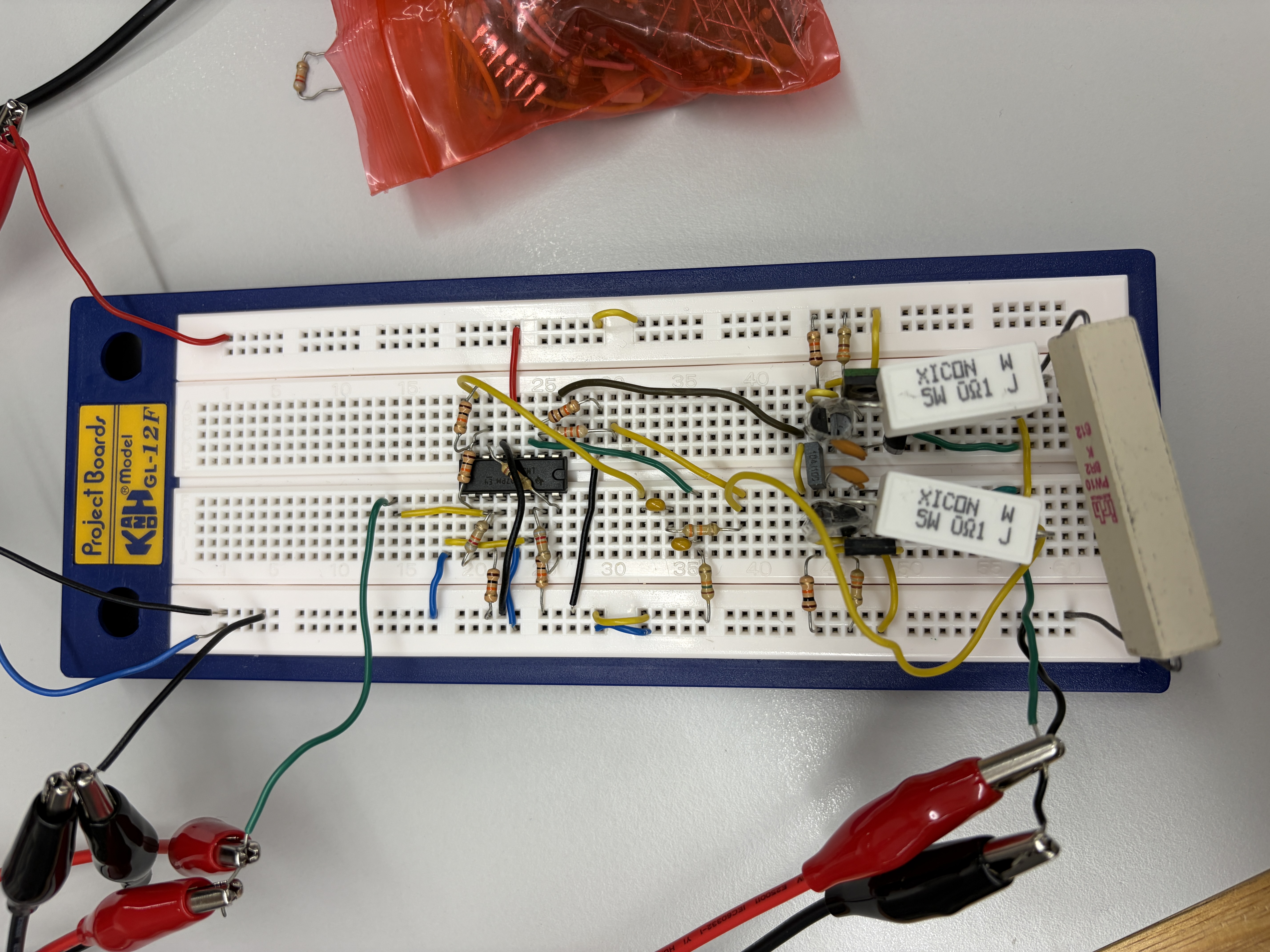
A site-native project entry using the existing photo and report already in the website files.

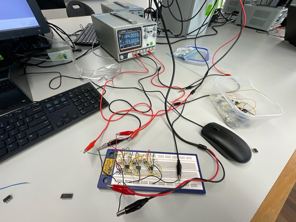
Audio amplifier circuit assembled on a breadboard

Small-Signal Audio Amplifier

A small-signal audio amplifier built and tested on breadboard, focused on analog circuit assembly, component selection, gain staging, and validating the signal path on real hardware.

Project 1

Arduino Uno IR sensor MAX9814 microphone KiCAD PCB LTSpice
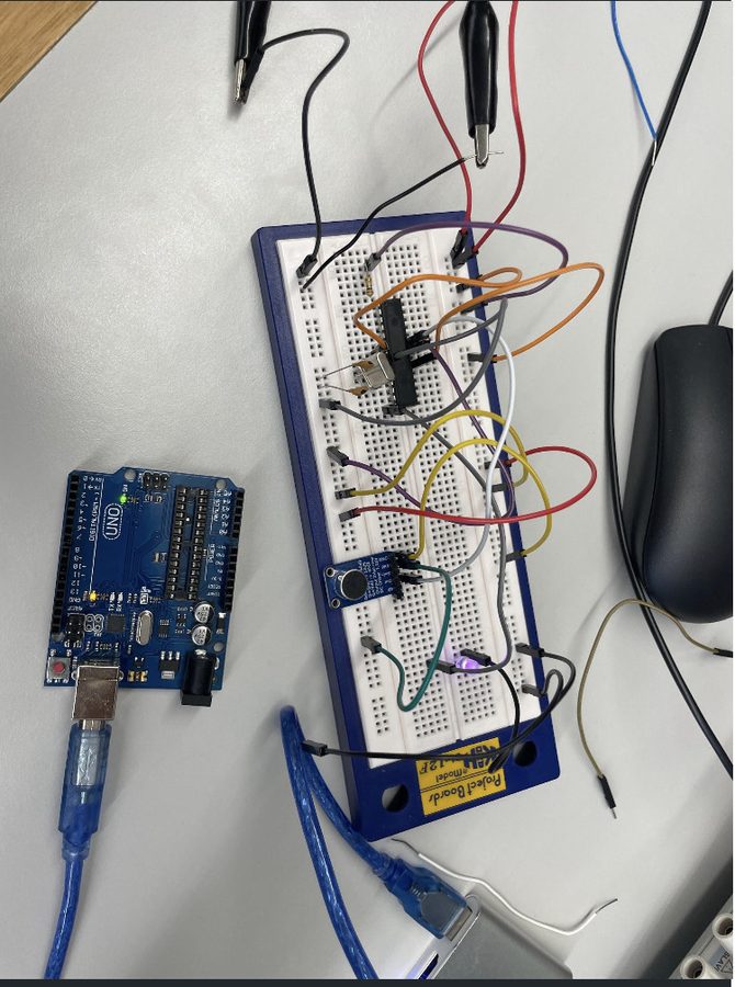
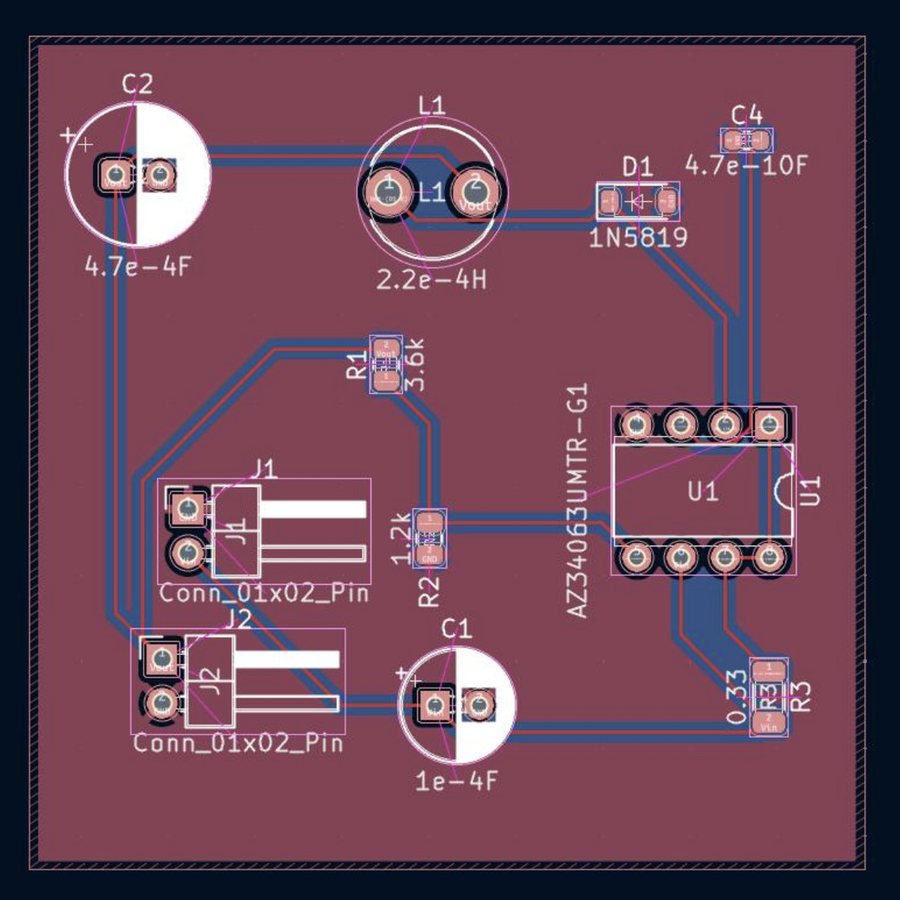
Touchless light switch breadboard with Arduino Uno and sensor module KiCAD PCB layout for the AZ34063U buck converter
Gesture input + PCB layout

Touchless Gesture-Controlled Light Switch

A contactless light switch activated by hand gesture or clap, designed to reduce wear and physical contact in shared spaces while running as a self-contained 9V battery-powered unit.

What

  • Contactless light switching through gesture or clap input.
  • Self-contained system with no bench supply required.
  • Built around real sensor modules and relay control.

How

  • Sharp GP2Y0D810Z0F IR sensor with 2-10 cm detection.
  • MAX9814 microphone module for clap activation.
  • ATmega328P C++ firmware for debounce, timing, and relay control.
  • AZ34063U buck converter PCB stepping 9V down to 5V.

Result

  • 60% false trigger reduction through filtering and reset timing.
  • 3-9.5 cm adjustable detection range using a trimpot.
  • ERC/DRC clean KiCAD PCB with BOM generated.

Project 2

Inverting buck-boost 555 timer PWM N-MOSFET LM741 supply rail
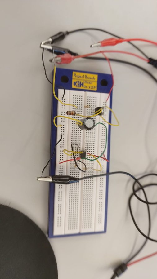
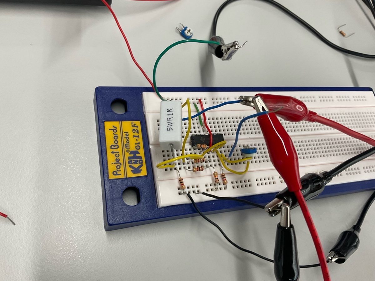
Negative power supply converter assembled on a breadboard Negative rail generation

LM741 Negative Power Supply

An inverting buck-boost converter that generates a stable -5V rail from a single positive supply, enabling dual-rail LM741 op-amp operation without an external signal generator.

What

  • Generate a stable negative rail from a positive DC input.
  • Support LM741 dual-rail operation under load.
  • Minimise ripple while keeping the build self-contained.

How

  • 1 mH inductor, N-MOSFET, 1N4148 diode, and 2200 uF output capacitor.
  • 555 timer clock at approximately 25 kHz for PWM switching.
  • Full LTSpice transient simulation before breadboard testing.

Result

  • -5.0V stable output under 50 mA load.
  • Output ripple below 320 mV.
  • Powered LM741 amplifier produced a 6.3V peak-to-peak sine wave.

Project 3

Active filters LM741 LTSpice AC analysis KiCAD 2-layer PCB
Analog active filter breadboard being tested on a lab bench LP / HP / BP outputs

Analog Filtering Circuit

A single-input, three-output active filter producing low-pass, high-pass, and band-pass outputs simultaneously from a +/-12V supply.

What

  • LP, HP, and BP active filter outputs from one input.
  • 1.2 kHz target cutoff frequency.
  • Four simultaneous hard specifications to satisfy.

How

  • Second-order active LP/HP topology for 40 dB/decade rolloff.
  • MFB bandpass topology with independent frequency, Q, and gain control.
  • Unity-gain buffers on outputs for output impedance at or below 1 kOhm.

Result

  • 1.2 kHz cutoff confirmed on oscilloscope.
  • Greater than 40 dB/decade rolloff against a 35 dB spec.
  • +/-1.5 dB passband ripple and ERC/DRC clean PCB.

Project 4

Current measurement 3-op-amp IA 0.1 Ohm shunt Variable gain
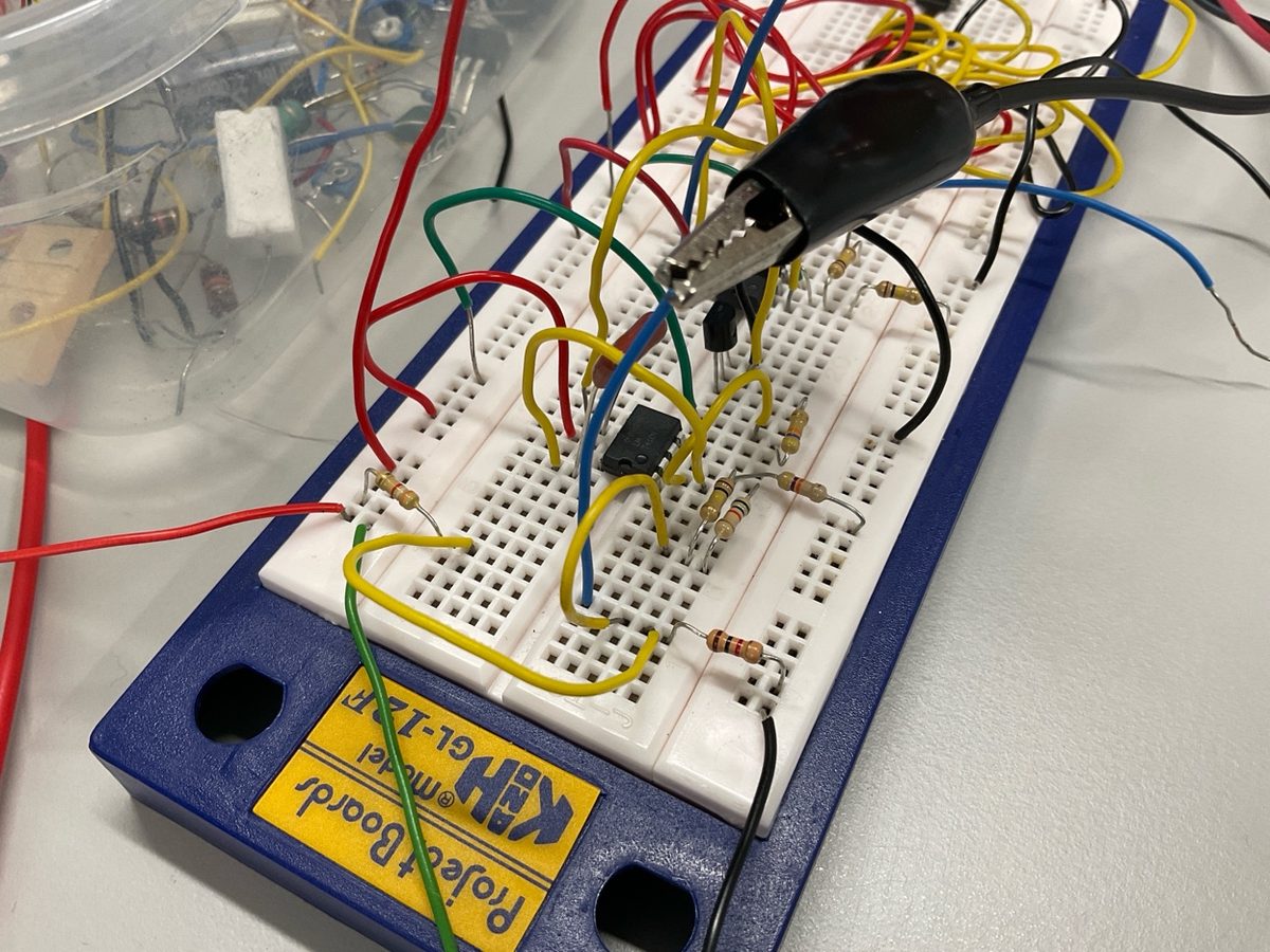
Current measurement amplifier breadboard with shunt resistor and test leads G = 10-100

Current Measurement Amplifier

A current-to-voltage amplifier with continuous variable gain from 10 to 100, designed for high-side or low-side measurement without rewiring.

What

  • Current-to-voltage amplifier for measurement applications.
  • Continuous gain control from 10 to 100.
  • Flat response target across 100 Hz to 10 kHz.

How

  • 0.1 Ohm shunt with 100 mV drop at 1A full scale.
  • 3-op-amp instrumentation amplifier rejects common-mode voltage.
  • Single trimpot adjusts gain; output buffer uses 1 kOhm series resistor.

Result

  • Gain adjustable from 10 to 100 with no component swap.
  • +/-3 dB response from 100 Hz to above 10 kHz.
  • High-side and low-side configurations validated.

Project 5

VCO Integrator core Schmitt trigger NMOS switching
Voltage-controlled oscillator breadboard with wiring and probe clips 1V to 4V control

Voltage-Controlled Oscillator

A VCO mapping 1V to 1 kHz and 4V to 10 kHz, with dual triangle and square wave outputs inside a 0-5V rail.

What

  • Linear control-voltage-to-frequency mapping.
  • Triangle wave and square wave outputs.
  • Output constrained to the 0-5V supply rail.

How

  • Integrator op-amp and capacitor create linear ramp.
  • Schmitt trigger comparator hysteresis defines thresholds.
  • NMOS discharges the integrator capacitor at each threshold crossing.

Result

  • 1-10 kHz output range met specification.
  • Linear monotonic mapping confirmed from 1V to 4V.
  • Both waveforms stayed within supply rail with stable operation.

Project 6

PAT testing Seaward PAC3760 DL AS/NZS 3760:2022 Compliance records
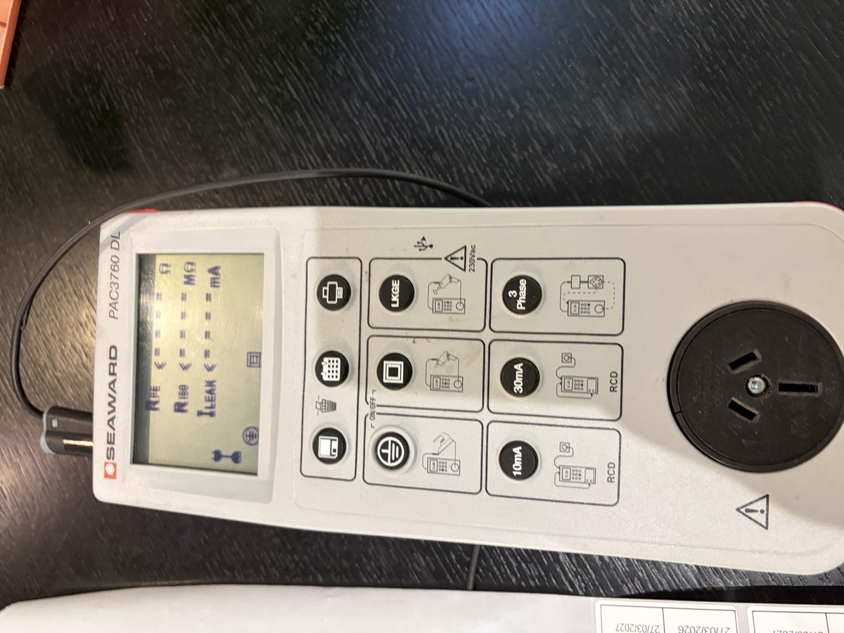
Seaward PAC3760 DL portable appliance tester RPE / RISO / ILEAK

Electrical Test & Tag

Portable Appliance Testing using a Seaward PAC3760 DL, applying AS/NZS 3760:2022 safety checks to in-service equipment across residential and commercial sites.

What

  • Visual inspection, earth bond, insulation resistance, and leakage current tests.
  • Systematic electrical safety inspection of in-service equipment.
  • Specification-driven pass/fail validation.

How

  • RPE earth resistance verifies chassis-to-earth continuity.
  • RISO applies 500 V DC to check insulation integrity.
  • ILEAK measures leakage current under normal operating voltage.

Result

  • AS/NZS 3760:2022 compliant test and tag records produced.
  • Unsafe appliances identified and quarantined before re-energisation.
  • Test registers and tag records maintained for audit readiness.

Technical Skills

Tools and methods used across the portfolio, grouped the same way as the original project document.

Hardware Design

  • Analog circuit design
  • Op-amp topologies: LM741, LM324
  • Active filter design: LP, HP, BP
  • Instrumentation amplifiers
  • DC-DC power converters

PCB Design

  • KiCAD schematic capture and ERC
  • PCB layout and DRC
  • 2-layer FR-4 boards
  • Ground pour strategy
  • Gerber export and BOMs

Simulation

  • LTSpice transient, AC, and parametric simulation
  • MATLAB and Simulink
  • ADS: Advanced Design System
  • Simulation-first methodology

Embedded & FPGA

  • C/C++ on ATmega328P
  • ADC, PWM, GPIO, interrupts
  • Sensor interfacing
  • Verilog, SystemVerilog, VHDL
  • Vivado and Quartus

Programming

  • C, C++, Python, MATLAB
  • MIPS Assembly
  • Git version control
  • Shell scripting

Field & Test

  • LV electrical installation
  • Solar and inverter commissioning
  • Oscilloscope, bench PSU, DMM
  • AS/NZS wiring standards